banner


How To Get Glass Out Of Moto Z2 Camera Lens

Introduction

If your Moto Z2 Force camera is damaged or broken, this guide will show you how to supplant it.

For your safety, discharge your battery beneath 25% before disassembling your phone. This reduces the gamble of a dangerous thermal effect if the bombardment is accidentally damaged during the repair. If your battery is swollen, take advisable precautions.

Alert: The screen assembly of this device is comprised of a rigid midframe and a flexible plastic display that tin divide apart during disassembly. Excessive heat on the brandish tin can likewise cause it to bubble up or warp, and this is very difficult to remedy. If you programme on reusing the screen associates, heed all warnings carefully and do not utilise whatsoever rut on the display.

  1. When separating the sides of the screen assembly from the device's frame, you will need to release five metal clips securing it in place. Three of these clips are located on the left side of the device, and two are located on the right side.

    • When separating the sides of the screen assembly from the device's frame, you lot will need to release five metal clips securing it in place.

    • Three of these clips are located on the left side of the device, and two are located on the right side.

    • You volition need to piece of work around these clips with your opening pick in order to fully release them.

    • You can either carefully slide an opening option around these clips, or leave a selection on one side of the prune while prying the other side with another pick.

  2. Insert a Jimmy or other metal tool between the right side of the plastic display and the metal frame, near the phone's side buttons. This may require a considerable amount of force. Push the tool as far down into the gap as you can, taking care to not scratch the chassis of your device in the process. Tilt the Jimmy downward while continuing to push it deeper into the gap to pry up the right side of the screen assembly.

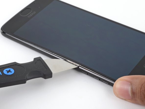
    • Insert a Jimmy or other metal tool between the correct side of the plastic display and the metallic frame, near the telephone'southward side buttons.

    • This may require a considerable corporeality of force. Button the tool equally far downward into the gap as y'all tin, taking intendance to not scratch the chassis of your device in the process.

    • Tilt the Jimmy downward while continuing to push it deeper into the gap to pry up the right side of the screen assembly.

    • Since the display on superlative of the screen associates is flexible and only fastened with a slight amount of agglutinative, you may end upward prying upwardly simply the display instead of lifting the entire assembly. If this occurs, remove the tool and try again, this time using more than down forcefulness to go underneath the entire associates.

    • Ensure your tool is behind the unabridged screen associates and not just the brandish. If washed correctly, you should notice the thin silver metal midframe come upwards with the plastic brandish (as pictured).

  3. With the Jimmy still inserted, insert an opening pick under the silver midframe, on top of the Jimmy in the same location Remove the Jimmy.

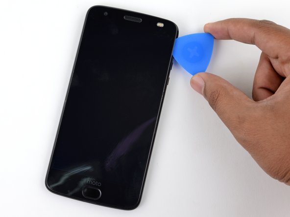
    • With the Jimmy still inserted, insert an opening pick nether the silverish midframe, on elevation of the Jimmy in the same location

    • Remove the Jimmy.

  4. Slide your opening pick all along the right side of the device to release the clips and adhesive securing the screen assembly. As you separate the lower part of the right edge, you should encounter the two metal clips mentioned previously. If you do not see or feel these clips, you are only separating the top half of the assembly! If so, press the screen back down into place and start again from the beginning of the screen removal process. As you separate the lower part of the right edge, you should encounter the two metal clips mentioned previously. If you do not see or feel these clips, you are only separating the top half of the assembly! If so, press the screen back down into place and start again from the beginning of the screen removal process.

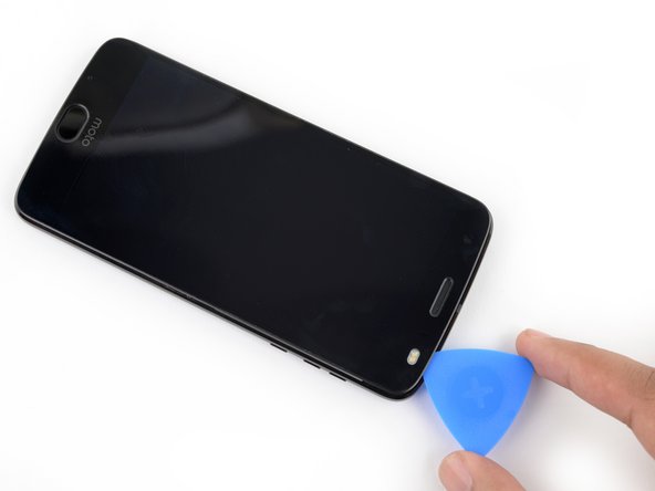
    • Slide your opening option all forth the right side of the device to release the clips and adhesive securing the screen assembly.

    • As you split the lower part of the correct edge, you should meet the 2 metal clips mentioned previously. If you exercise non see or feel these clips, you are only separating the top half of the associates! If then, press the screen back down into place and start over again from the beginning of the screen removal process.

  5. Once the screen assembly's right edge is separated, slide your pick around the bottom right corner of the device so it is underneath the bottom edge of the assembly. Slide the tool all along the bottom edge of the phone to slice through the adhesive securing the screen assembly and release the plastic clips. These plastic clips should snap free much easier than the metal ones you released earlier.

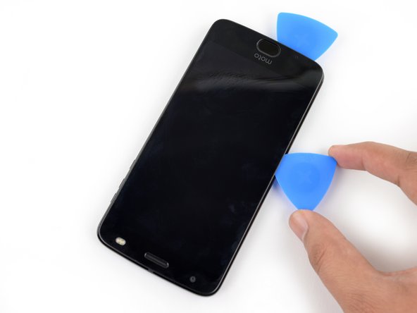
    • Once the screen assembly'due south correct border is separated, slide your choice around the bottom right corner of the device then it is underneath the bottom edge of the associates.

    • Slide the tool all along the lesser edge of the phone to slice through the adhesive securing the screen associates and release the plastic clips.

    • These plastic clips should snap free much easier than the metallic ones yous released earlier.

    • Leave your tool underneath the bottom edge of the screen associates to preclude it from re-adhering to the frame. Continue to the next stride with a new tool.

  6. When separating the left side of the screen assembly, take care to not snag the display cable located on the left edge near the bottom of the display. When separating the left side of the screen assembly, take care to not snag the display cable located on the left edge near the bottom of the display.

    • When separating the left side of the screen associates, take care to non snag the display cable located on the left edge well-nigh the bottom of the display.

  7. Insert another opening pick underneath the bottom edge of the screen assembly and slide it around the bottom left corner of the device so it is underneath the assembly's left edge. Slide your tool all along the left edge of the phone to separate the metal clips and adhesive securing the screen assembly. Like before, ensure you are separating the entire assembly by identifying the three metal clips on the right edge of the device.

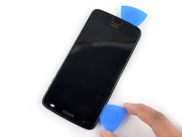
    • Insert another opening pick underneath the bottom edge of the screen assembly and slide information technology around the bottom left corner of the device so it is underneath the associates's left border.

    • Slide your tool all along the left edge of the telephone to separate the metal clips and adhesive securing the screen assembly.

    • Like before, ensure yous are separating the entire assembly by identifying the three metal clips on the correct edge of the device.

  8. Slide your tool around the top edge of the screen assembly and slice all along it to slice through its adhesive. Take care to not insert your tool more than ~4 mm past the edge of the display to prevent damaging the front facing sensor array. Take care to not insert your tool more than ~4 mm past the edge of the display to prevent damaging the front facing sensor array.

    • Slide your tool around the pinnacle edge of the screen assembly and slice all along it to piece through its adhesive.

    • Take care to not insert your tool more than than ~4 mm past the border of the display to prevent damaging the front facing sensor assortment.

  9. There are two large pads of adhesive securing the screen assembly near the top edge but further past the 4 mm that have already been sliced through. The front facing sensor array and cable surround the right patch of adhesive from the top and right, so prying or slicing from the top or right edge may damage the cable. The following steps will describe how to separate the adhesive from the left edge.

    • There are two large pads of agglutinative securing the screen assembly well-nigh the pinnacle border merely further past the 4 mm that have already been sliced through.

    • The front end facing sensor array and cable surround the correct patch of adhesive from the elevation and right, so prying or slicing from the top or right edge may damage the cable. The following steps will describe how to separate the adhesive from the left edge.

  10. Apply a small amount of high concentration (>90%) isopropyl alcohol underneath the screen assembly's left edge, near the top of the device.

    • Apply a small corporeality of high concentration (>90%) isopropyl alcohol underneath the screen assembly's left edge, most the superlative of the device.

    • Allow the device to sit upright on its correct edge for ~5 minutes to allow the alcohol to penetrate and weaken the adhesive.

  11. Insert an opening pick as deep as possible under the top left corner of the screen assembly to slice through the left patch of adhesive. Insert an opening pick as deep as possible under the top left corner of the screen assembly to slice through the left patch of adhesive. Insert an opening pick as deep as possible under the top left corner of the screen assembly to slice through the left patch of adhesive.

    • Insert an opening pick equally deep as possible under the top left corner of the screen assembly to slice through the left patch of adhesive.

  12. Slowly and carefully slide the flat end of a spudger under the left edge of the screen assembly. Gradually insert it deeper to pry up the top edge of the assembly and release the right patch of adhesive. Add more isopropyl alcohol as needed, but take care to not use too much, as this may dissolve other adhesives in the device that would preferably remain sticky. Give any additional alcohol some time to penetrate the adhesive before continuing. Only pry up the assembly enough to slide the spudger underneath  and release the adhesive. The assembly is still attached via the display cable, and prying the left side too far upward may damage it.

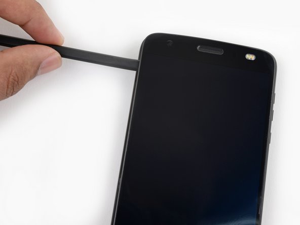
    • Slowly and advisedly slide the flat stop of a spudger under the left edge of the screen assembly. Gradually insert it deeper to pry up the acme edge of the assembly and release the right patch of adhesive.

    • Add more than isopropyl alcohol as needed, only accept care to not use also much, as this may dissolve other adhesives in the device that would preferably remain viscid. Give any additional alcohol some time to penetrate the agglutinative before standing.

    • But pry up the assembly plenty to slide the spudger underneath and release the adhesive. The associates is still attached via the brandish cablevision, and prying the left side besides far upward may damage it.

  13. Lift the screen assembly from the right edge and swing it open. It is still attached to the phone chassis at the lower left edge, so do not fully remove it yet. If the screen assembly remains stuck, slice the adhesive repeatedly as needed.

    • Lift the screen associates from the right edge and swing information technology open. It is all the same attached to the telephone chassis at the lower left border, then exercise not fully remove information technology yet.

    • If the screen assembly remains stuck, piece the adhesive repeatedly as needed.

  14. Use a pair of tweezers to remove the black piece of tape covering the battery connector. Try your best to keep this piece of tape intact and retain it for reassembly.

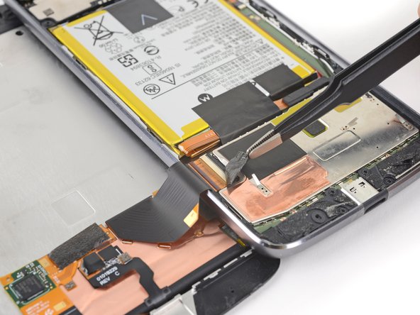
    • Use a pair of tweezers to remove the blackness piece of tape covering the battery connector.

    • Try your best to keep this slice of tape intact and retain it for reassembly.

  15. Use a spudger to pry up the locking tab on the display cable's ZIF connector. Use a pair of tweezers to slide the display ribbon cable out of the connector. Use a pair of tweezers to slide the display ribbon cable out of the connector.

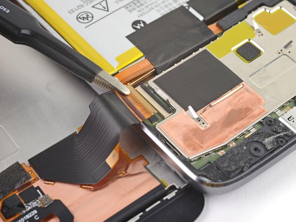
    • Employ a spudger to pry up the locking tab on the display cable's ZIF connector.

    • Utilize a pair of tweezers to slide the display ribbon cable out of the connector.

  16. Remove the screen assembly.

    • Remove the screen associates.

    • When putting your device back together, be certain to reconnect the brandish, turn the device on, and test all functionality before closing your device and sealing it support.

    • During reassembly, pause here and replace the agglutinative around the edges of the display if you are reusing your screen assembly.

    • After closing your device dorsum up, stack something heavy, similar a textbook or ii, on top of the device for 30-60 minutes. This ensures a strong adhesive bond.

    • Utilize a pair of tweezers to remove the two black pieces of tape securing the battery.

    • Take intendance to go along these tape pieces intact so they can be reused.

    • While not crucial, this tape helps dissipate rut from the battery. They won't stick back downwards by themselves, merely if the record pieces are still more often than not intact, re-attach them with some adhesive during reassembly.

  17. Use an opening pick to pry up the small black bracket covering the battery connector. It is secured with a small bit of adhesive. Use a pair of tweezers or your fingers to remove the bracket. Use a pair of tweezers or your fingers to remove the bracket.

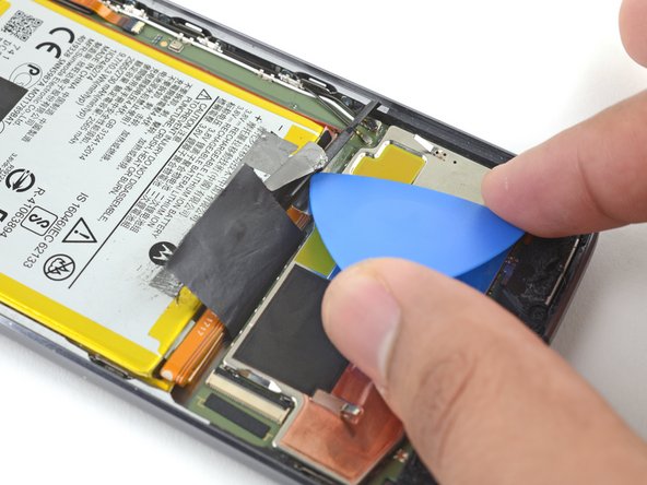
    • Use an opening selection to pry upwards the small blackness bracket covering the battery connector. Information technology is secured with a minor bit of adhesive.

    • Use a pair of tweezers or your fingers to remove the subclass.

  18. Use a spudger to pry up and disconnect the battery connector. Use a spudger to pry up and disconnect the battery connector.

    • Use a spudger to pry up and disconnect the bombardment connector.

  19. Unscrew the three 1.7mm T4 screws from the speaker. Unscrew the three 1.7mm T4 screws from the speaker. Unscrew the three 1.7mm T4 screws from the speaker.

    • Unscrew the three one.7mm T4 screws from the speaker.

  20. Use the nylon spudger to lift and remove the speaker from the phone chassis. Use the nylon spudger to lift and remove the speaker from the phone chassis. Use the nylon spudger to lift and remove the speaker from the phone chassis.

    • Apply the nylon spudger to lift and remove the speaker from the phone chassis.

  21. Insert the flat end of the nylon spudger on the side of the rear facing camera closest to the battery. Pry up the camera by pushing down on the spudger until the camera pops up.

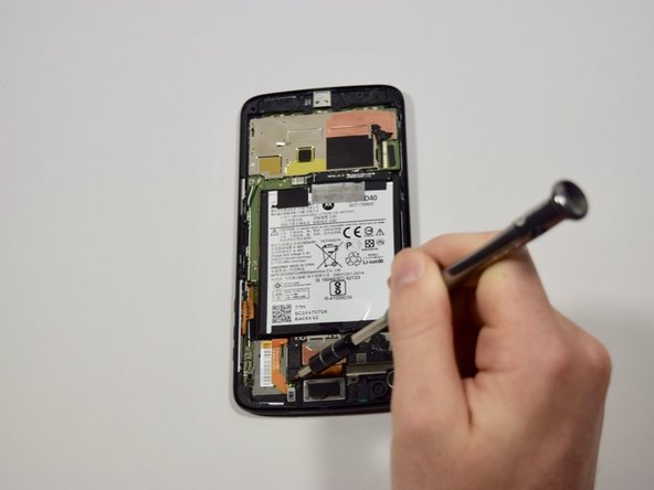
    • Insert the flat end of the nylon spudger on the side of the rear facing camera closest to the bombardment.

    • Pry up the camera past pushing downwardly on the spudger until the camera pops upward.

  22. Insert the flat end of the nylon spudger underneath the black lock. Unlock the ribbon cable by pulling up on the lock with the nylon spudger.

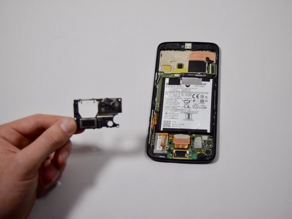
    • Insert the apartment stop of the nylon spudger underneath the black lock.

    • Unlock the ribbon cable past pulling upward on the lock with the nylon spudger.

    • Separate the rear facing camera from the lath past pulling gently towards the bottom of the phone.

Conclusion

To reassemble your device, follow these instructions in reverse order.

Team

Embed this guide

Choose a size and copy the lawmaking below to embed this guide as a small-scale widget on your site / forum.

Preview

Source: https://www.ifixit.com/Guide/Motorola+Moto+Z2+Force+Rear+Facing+Camera+Replacement/103317

Posted by: williamssignitere.blogspot.com

0 Response to "How To Get Glass Out Of Moto Z2 Camera Lens"

Post a Comment

Iklan Atas Artikel

Iklan Tengah Artikel 1

Iklan Tengah Artikel 2

Iklan Bawah Artikel